Autocad Copy a Surface to Another Drawing
Create/Edit Surface
Introduction
Use this command to create and update surfaces created from a variety of data sources. Normally this command will be used to create existing surface data for extraction of levels to use in a design, however it can be used to construct a surface from any assortment of 3D data.
The surface is managed in the drawing as an object (when selected, the AutoCAD Properties dialogue identifies it as an AutoCAD Point object) - selecting the object and right clicking will display the shortcut menu and include commands for updating/editing surfaces.
The surface creation form contains three (3) parts:
- Inputs: 3D data is selected as data for construction of the surface;
- Outputs: Sets display outputs required, such as contours, contour labelling and 3D faces;
- Statistics: Provides various statistics about the surface after it has been built.
Supported data sources are as listed in the Inputs section of the form, as detailed below. In most cases the user selects layers in the drawing that contain 3D data required in the surface.
This command can be used to change the surface display in the drawing. This form is modeless - users can freely move around and undertake AutoCAD commands in the drawing, with this form showing on screen or minimised.
Use the Windows Close button (x at the top right) to close the form.
Surfaces can be simply rebuilt by re-running this command and clicking to recreate the surface. It is recommended to Build Surface whenever the data inputs change.
While the Surfaces form is open, users can still work in the AutoCAD drawing and use any AutoCAD commands.
Notes:
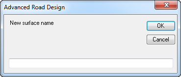
- Upon first running this command, or when there are no surfaces in the drawing, the user will be prompted to create a new surface by typing in a surface name.
- The default Surface Style applied to any new surface can be set by the user via the Active Drawing Settings command in the Modelling tab.
- With exception to the points file import, all data added to the surface is a 'live' read of the information - if the information is removed from the drawing, upon rebuild of the surface it will update to reflect the removed data.
- When 3D Face data is added, no other data can be added that may conflict with the surface triangles resulting from the 3D Faces.
- The Surface object display (not including any labelling) is managed as an AutoCAD point object - when it is selected in the drawing the entire object highlights.
- To share the surface outputs with non-CSD users, use the Make AutoCAD Objects command to output contour polylines and 3D faces into the drawing.
- Surface names must not include any commas (,)
Notes for Civil 3D Users
Whilst this tool can be used to create surveyed (existing) surfaces, typically Civil 3D users will create the design surfaces as Civil 3D surface objects.
By default design surfaces will be created as CSD Surfaces, and designers should make themselves familiar with the Outputs tab in order to manage the display output of the CSD surfaces.
Details
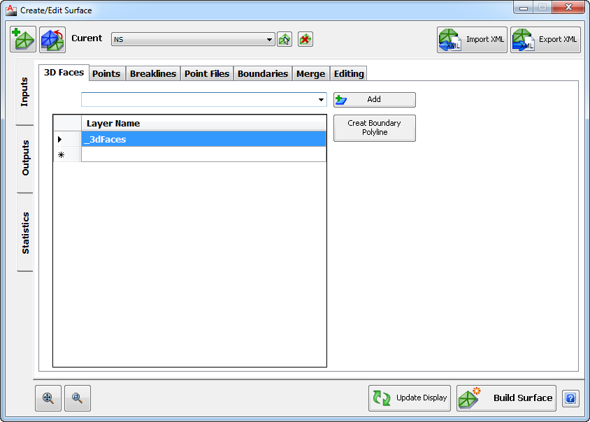
Upon selecting the command the following form is displayed:
 | |||||||||||||||||||||||||||||||||||||||||||||||||||||||||||
 New Surface New Surface | Creates a new surface. Note: Do not use commas in the name of the surface. Upon selecting the command the following form is displayed:
| ||||||||||||||||||||||||||||||||||||||||||||||||||||||||||
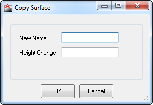
 Copy Surface Copy Surface | Creates a copy of the current surface, inclusive of all the Surface Inputs and Outputs. An independent copy is created in this process. Upon selecting the command the following form is displayed:
| ||||||||||||||||||||||||||||||||||||||||||||||||||||||||||
| Surface Name Pick List | Select any Surface from the list to enable editing and creation/output of the selected surface. | ||||||||||||||||||||||||||||||||||||||||||||||||||||||||||
 Pick from Drawing Pick from Drawing | Pick a surface from the drawing to edit. | ||||||||||||||||||||||||||||||||||||||||||||||||||||||||||
 Delete Current Surface Delete Current Surface | Deletes the currently highlighted surface. Note: No confirmation warning message is displayed. | ||||||||||||||||||||||||||||||||||||||||||||||||||||||||||
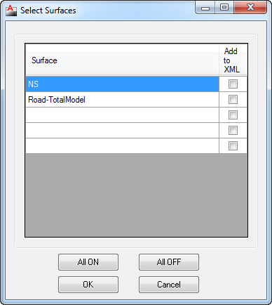
 | Click here to import a surface/s from a Land XML file. A navigation window will display to enable selection and opening of the file. Upon selecting a Land XML file, the software will scan the file for all surfaces and include them in the Surfaces list. Note: An imported surface cannot be edited by adding any Input data. After the file has been opened the following is displayed: | ||||||||||||||||||||||||||||||||||||||||||||||||||||||||||
 | Exports the selected surface/s to a Land XML file, ready for import into other programs supporting the Land XML file format. Upon selecting the command the following is displayed:
| ||||||||||||||||||||||||||||||||||||||||||||||||||||||||||
 Zoom Extents Zoom Extents | Zoom to the extents of the selected (current) surface. | ||||||||||||||||||||||||||||||||||||||||||||||||||||||||||
 Zoom and/or Pan Zoom and/or Pan | Use the Mouse wheel to zoom and pan in the drawing. Press ESC to finish and return to the Create/Edit Surface form. | ||||||||||||||||||||||||||||||||||||||||||||||||||||||||||
 | Forces the surface to redisplay - this is required when certain outputs are selected, such as slope arrows, slopes, heights and directions. | ||||||||||||||||||||||||||||||||||||||||||||||||||||||||||
 | Create/Update the surface model. This forces a recalculation of the surface using all the data Inputs and a redisplay of the Outputs. | ||||||||||||||||||||||||||||||||||||||||||||||||||||||||||
 Help Help | Display Help on this command. | ||||||||||||||||||||||||||||||||||||||||||||||||||||||||||
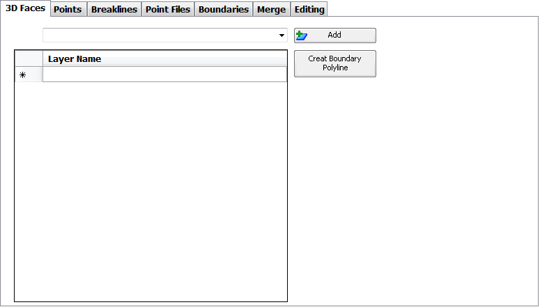
| Inputs Control (as shown above) | Select all of the 3D data required for the construction of the surface. Upon selection of the Inputs Control tab a number of different surface input options will be displayed and include: | ||||||||||||||||||||||||||||||||||||||||||||||||||||||||||
| 3D Faces |
| ||||||||||||||||||||||||||||||||||||||||||||||||||||||||||
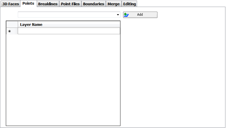
| Points |
| ||||||||||||||||||||||||||||||||||||||||||||||||||||||||||
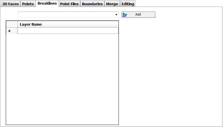
| Breaklines |
| ||||||||||||||||||||||||||||||||||||||||||||||||||||||||||
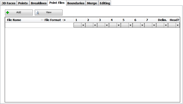
| Point Files |
| ||||||||||||||||||||||||||||||||||||||||||||||||||||||||||
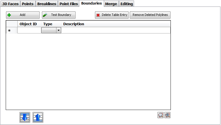
| Boundaries |
| ||||||||||||||||||||||||||||||||||||||||||||||||||||||||||
| Merge | To use this command, first create a NEW surface, then choose the two (2) surfaces that are to be combined. The Initial Surface should be larger the the Surface to Merge. Once the 2 surfaces have been selected, press Build Surface.
| ||||||||||||||||||||||||||||||||||||||||||||||||||||||||||
| Editing | |||||||||||||||||||||||||||||||||||||||||||||||||||||||||||
| Outputs Control | The Outputs Control tab sets out how the surface should display in the drawing, as well as controlling how the surface is built. Upon selection of the Outputs Control tab a number of different surface options will be displayed and include: | ||||||||||||||||||||||||||||||||||||||||||||||||||||||||||
| Contours & Mesh | |||||||||||||||||||||||||||||||||||||||||||||||||||||||||||
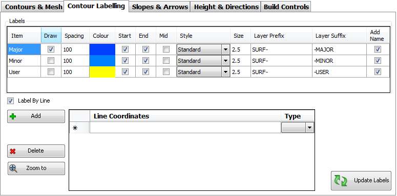
| Contour Labelling |
| ||||||||||||||||||||||||||||||||||||||||||||||||||||||||||
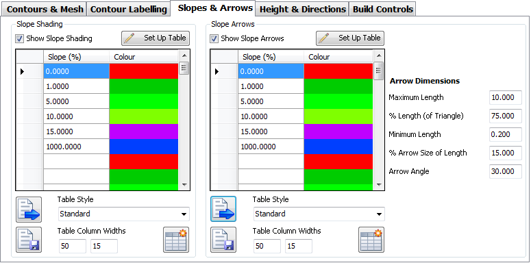
| Slopes & Arrows | When selecting this tab for the first time tab, the default for both options is OFF, so that image below does not represent the 'start' condition. Once the Show box is ticked, the information, as shown, will be displayed.
| ||||||||||||||||||||||||||||||||||||||||||||||||||||||||||
| Height & Directions | When selecting this tab for the first time tab, the default for both options is OFF, so that image below does not represent the 'start' condition. Once the Show box is ticked, the information, as shown, will be displayed.
| ||||||||||||||||||||||||||||||||||||||||||||||||||||||||||
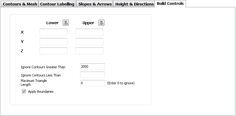
| Build Controls | Users can control how data is processed in the creation of the surface.
| ||||||||||||||||||||||||||||||||||||||||||||||||||||||||||
 Load Style Load Style | Loads a pre-set Surface Style - the Surface Style sets Output controls for the surface. | ||||||||||||||||||||||||||||||||||||||||||||||||||||||||||
 Save Style Save Style | After setting up the Outputs as desired, use Save Style to store the Output settings for re-use. | ||||||||||||||||||||||||||||||||||||||||||||||||||||||||||
| Loaded Style: | After Load Style has been used, the SDF filename loaded is displayed here. | ||||||||||||||||||||||||||||||||||||||||||||||||||||||||||
| Statistics | Displays Statistics about the surface. Upon selecting the Statistics Control tab, the following form is displayed. The form is initially empty, data will only appear after the Update button has been selected. | ||||||||||||||||||||||||||||||||||||||||||||||||||||||||||
| |||||||||||||||||||||||||||||||||||||||||||||||||||||||||||


 Move Down
  Move Up
  Zoom to Boundary
  Show All Boundaries
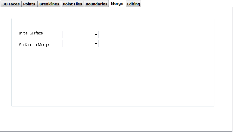


 Load Style
  Save Style
  Create Table
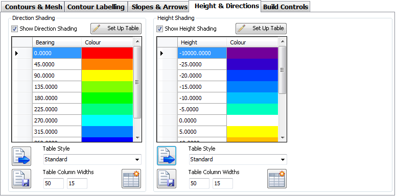
 provided for each bound column.
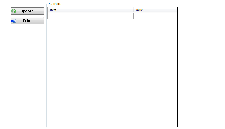


Range Table Creation
For each of the four (4) analysis that can be carried out on a surface, this option provides a way to generate the ranges based on the statistics for the surface being analysed.
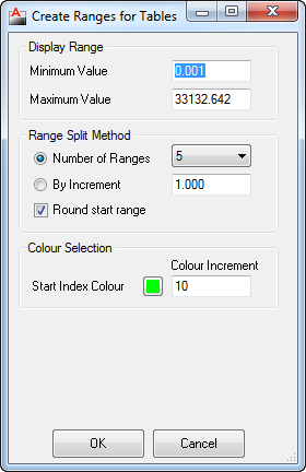 | |
| Display Range | Initially displays the Minimum and Maximum value based on the Analysis type and Surface Data. |
| Minimum Value | The minimum or lower value for this range. This box may be changed to the required lower limit for analysis. |
| Maximum Value | The maximum or highest value for this range. This box may be changed to the required upper limit for analysis. |
| Range Split Method | Provides two (2) methods for generating divisions between the minimum and maximum values set above. Only one (1) method can be selected. |
| Number of Ranges | Select this radio button to create division based on the number chosen in the adjoining drop list. Any number from 1 to 16 may be used. Equal division ranges will then be generated to suit the number. |
| By Increment | Select this radio button to create division based on the increment entered in the adjoining drop list. Ranges will then be generated to suit the incement. |
| Round Start Range | Toggle On/Off to round the Start or minimum value. |
| Colour Selection | Sets criteria to assign colours to the ranges required. |
| Start Index Colour | Click on the Colour swatch to select the starting colour (number) from any available AutoCAD colour. |
| By Increment | Specify an increment to add to the starting or previous colour number for next range. For example, if 1 (red) was chosen as the start, and in the increment was set to 3, the next range would be assigned colour 4 (cyan), the next range would be given colour 7 (white) |
| OK | Apply and exit and return to the analysis form, with an updated range table base on the selection made. |
| Cancel | Exit the form without creating any data. |
farnsworthsliquichater.blogspot.com
Source: https://www.help.civilsurveysolutions.com/OnlineHelp/CSD_Siteworks/SurfaceHelp/Commands/Create-EditSurface/Create-EditSurface.htm
Belum ada Komentar untuk "Autocad Copy a Surface to Another Drawing"
Posting Komentar